
From the creation of the first inrush current limiter series, back in 1994, Ametherm knew that having logic behind the series naming convention would be important. Not only for organizational means but also to easily identify the components of the inrush current limiters and NTC thermistor temperature sensors.
Both product lines, the inrush current limiters and NTC thermistor temperature sensors, have stringent guidelines created to get the most accurate description of each product in the series. From the identifying series alpha code to diameter to resistance and more, there is a lot of information you can get from these part numbers.
INRUSH CURRENT LIMITER CODING
With the inrush current limiter product line, most of the parts follow the same naming convention (one exception being the RTI line).
Beginning with the series alpha code, the first two letters are then followed by the disc diameter in millimeters (mm). The last five digits are broken up into two sections. The first being the measurement of the resistance at 25 degrees Celsius, with this either having an “R” being used as a decimal point or the multiplier following the resistance. Finishing with the tail end is the maximum steady-state current. An example of both, with and without “R,” can be found in the diagrams below.
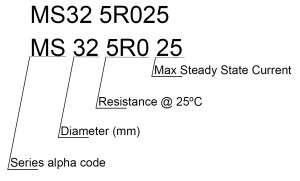
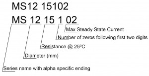
On occasion, there may be modifications to a specific inrush current limiter part. These will have a dash followed by an alpha code. (i.e., SL15 7R005-L)
The alpha code denotes:
A – Inside Crimp
B – Outside Crimp
C – Customer Marking
H – Half Coat
J – Special Lead Cut
L – Larger Lead Diameter
NTC THERMISTOR TEMPERATURE SENSOR CODING
The NTC thermistor temperature sensor product line labeling procedure is a bit different than that of the inrush current limiter product line. There are set rules for each individual series within the NTC thermistor temperature sensing line. With each series within this product line being is too varied to have a single way of labeling the entire line.
The PAN (Probe Assembly NTC) series houses five-part types, each with a different ending alpha character where:
E = Epoxy
R = Ring Lug
W = Threaded Metal Tubing and Hex
H = Closed-End Metal Tubing
T = Threaded Tip and Hex
Trailing the alpha code is six numbers. These represent the resistance with a multiplier and beta value (which would be followed by a zero).
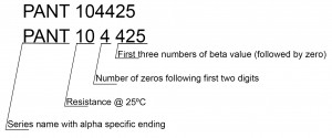
Glass-Encapsulated Thermistors Series
The DG glass-encapsulated thermistor series part number labeling is the same as the PAN series, breaking each part down by series name, the resistance with a multiplier, and beta value (which would be followed by a zero).
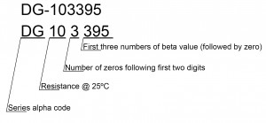
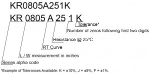
KR and TR Series
The KR and TR thermistor series part number labeling starts with the model prefix, the size of the part is next (length and width in inches), followed by the RT curve, then the resistance with a multiplier, finishing out with tolerance.
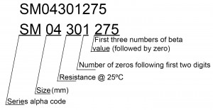
 SM Series
The SM Series thermistor series part number labeling starts with the model prefix, the size of the part is next (in mm), followed by the resistance with a multiplier, and finally the first three digits of beta (which would be followed by a zero).
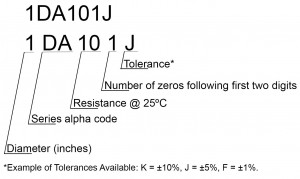
Disc and Chip Style Series
The disc and chip style NTC thermistor series part number labeling starts with the size of the part, in inches (.1, .2, etc.), then goes to the alpha code for the series, followed by the resistance with a multiplier, and ending with the tolerance.
As you can see, the naming conventions for both our NTC thermistor temperature sensing and inrush current limiting series took some time and thought. Ensuring enough information was included without making the part numbers too long.
Now that you know how to read the part numbers go ahead and check out the entire NTC thermistor temperature sensing and inrush current limiting series line.
Keep in mind free samples are available and our engineers are always here to answer any questions you may have.


