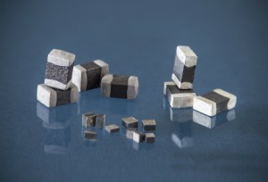
RTI manufactures precision resistance-temperature SMD thermistors. Standard values from 250 ohms to 150,000 ohms are available. As with RTI’s disc and chip thermistors, SMD thermistors are suitable for temperature sensing applications over a wide range of resistance values and temperature coefficients. SMD’s operating temperature range is from -55°C to +150°C. Dissipation constant is 2mW/°C, with a maximum power rating of 250mW @ 25°C.
Applications
Most semiconductors and the circuits comprised of them exhibit a positive temperature coefficient. NTC thermistors are well suited for compensating these responses to temperature changes. It is important to match the temperature of the compensating NTC thermistor to that of the component responsible for the temperature response.
RTI’s SMD temperature measurement NTC sensors can operate over a wide temperature range (-55 to +150°C). They are stable throughout a long lifetime, and are small and comparatively inexpensive. Typically, they have negative temperature coefficients between -3.3 and -4.7%/°C at 25°C. RTI’s SMD style thermistors are used in many applications that require a high degree of accuracy and reliability.
Features:
- Standard Sizes
- High Sensitivity
- Accurate & Stable
- Wide Ohmic Value Range
- Fast Thermal Response Time
Popular Applications:
- LED Control
- Temperature Compensation
- Power Transistor Stabilization
- Temperature Measurement & Control
Selection Considerations for SMD NTC Devices
- To determine the nominal resistance value of a thermistor at a specified temperature, multiply its RT/R25 value for the desired temperature and R-T curve from the table on NTC Resistance/Temperature Conversion Tables by its nominal resistance value at 25°C. As an example, the nominal resistance value at 80°C for a thermistor with the part number KR0805B103K is 10,000 times 0.157, the RT/R25 value in the R-T Curve “B” in the table under NTC Resistance/Temperature Conversion Tables.
- Standard resistance tolerances at 25°C for RTI’s SMD thermistors is ±10% and is indicated in its part number by the addition of the suffix K. To determine the resistance value at other than 25°C, add the appropriate DEV value from the NTC resistance/Temperature Conversion Tables to its resistance tolerance at 25°C. For example, the resistance tolerance at 80°C for a thermistor with part number KR0805B103K is ±10% ±3.0%, the DEV value from the R-T Curve “B” Table.
- Although standard sizes, resistance values and tolerances are listed on SMD Standard Products and Sizes, custom sizes, resistance values and tolerances are available depending on the application and volume requirements.
Consideration Notes:
- Calculate the DEV for R@T
- Review Power Dissipation
- Determine Required Accuracy
- Review Power Dissipation
- Select Required Resistance Values & Temperature Coefficient
KR SERIES
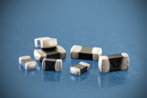
Configuration Options:
- Standard EIA Sizes Available
- Silver Palladium Terminations
- Bulk or Tape and Reel Packaging
- Two-Sided or Wraparound Terminations
KR Series Size Chart
| Size | 0805 | 1206 | ||
| Units | Inches | Millimeters | Inches | Millimeters |
| W | 0.049 ±0.008 | 1.240 ±0.200 | 0.063 ±0.008 | 1.600 ±0.200 |
| H | 0.051 Maximum | 1.300 Maximum | 0.059 Maximum | 1.500 Maximum |
| L | 0.079 ±0.008 | 2.000 ±0.200 | 0.126 ±0.008 | 3.200 ±0.200 |
| B | 0.008 Minimum | 0.200 Minimum | 0.008 Minimum | 0.200 Minimum |
KR Series Product Chart
| Part Number Size 0805 | Part Number Size 1206 | Resistance @ 25°C ±10% (Ohms) | Temperature Coefficient ( |
| KR0805A251K | KR1206A251K | 250 | -3.3%/°C |
| KR0805A501K | KR1206A501K | 500 | -3.3%/°C |
| KR0805J102K | KR1206J102K | 1.0K | -3.5%/°C |
| KR0805J252K | KR1206J252K | 2.5K | -3.5%/°C |
| KR0805B502K | KR1206B502K | 5.0K | -3.9%/°C |
| KR0805B103K | KR1206B103K | 10K | -3.9%/°C |
| KR0805C203K | KR1206C203K | 20K | -4.4%/°C |
| KR0805C253K | KR1206C253K | 25K | -4.4%/°C |
| KR0805C503K | KR1206C503K | 50K | -4.4%/°C |
| KR0805W104K | KR1206W104K | 100K | -4.7%/°C |
| KR0805W154K | KR1206W154K | 150K | -4.7%/°C |
KR Series Ordering Information
| KR = Model | 0805 =Size | A = R-T Curve | 251 = Resistance* | K = Tolerance** | X = Termination*** |
* Resistance value: First two digits are resistance value, third is the number of zeroes. Example: 251 = 250 ohms.
** Tolerances available: K = ±10% and J= ±5%.
***Terminations: No letter = Palladium Silver (Consult factory for optional terminations)
STC SURFACE MOUNT AND NTC CHIP THERMISTORS
Well suited for Temperature Measurement, Compensation and Control. 
- Fan Motors
- Fluid Levels
- Hybrid Circuits
- Robotic Assemblies
- Temperature Sensors used in a wide range of end products
STC Surface Mount & NTC Chip Thermistor Key Benefits
- RoHS Compliant
- Wide Range TCR Values
- Precision tolerance to 1%
- Fast Thermal Response Time
- High Accuracy Temperature Measurement
- Great alternative to thermocouples in precision circuits
- Available in sizes as small as 0.50 mm by 0.50 mm by 0.43 mm
- Wide range of resistance values at at 25 °C from 100 Ω to 5000 Ω
- High-Temperature Operation to + 150 °C
*For increased reliability, the device’s electrode surface is available in gold to prevent oxidation
| STC Device Specification Table: | ||||
|---|---|---|---|---|
| Series | Resistance @ 25 °C (Ω) | Size (mm) | Resistance ratio | Beta (°K) |
| STC0134-X | 100 to 680 | 0.58 x 0.58 x 0.76 to 1.0 x 1.0 x 1.7 | 5.3 (±5%) | 3000 |
| STC0138-X | 700 to 5000 | 0.89 x 0.89 x 0.97 to 1.3 x 1.3 x 1.6 | 6.9 (±3%) | 3523 |
| STC0143 | 500 | 0.50 x 0.50 x 0.43 | 5.3 (±3%) | 3000 |
| STC0144-X | 150 to 500 | 0.64 x 0.64 x 0.33 to 0.76 x 0.76 x 0.28 | 5.3 (±3%) | 3000 |
TR SERIES
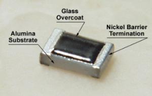
Standard EIA Sizes Available
Nickel Barrier Terminations
Bulk or Tape and Reel Packaging
Two-Sided or Wraparound Terminations
TR Size Chart
| Size |
0603 |
0805 |
||
| Units | Inches | Millimeters | Inches | Millimeters |
| Length | 0.063 ±0.006 | 1.60 ±0.150 | 0.080 ±0.008 | 2.00 ±0.20 |
| Width | 0.0315 ±0.006 | 0.80 ±0.15 | 0.050 ±0.004 | 1.25 ±0.10 |
| Height | 0.020 ±0.004 | 0.50 ±0.10 | 0.020 ±0.004 | 0.50 ±0.10 |
| Termination | 0.0012 ±0.0079 | 0.30 ±0.2 | 0.0016 ±0.008 | 0.40 ±0.20 |
TR Standard Product Chart
| Part Number Size 0603 | Part Number Size 0805 | Resistance @ 25 °C ± 10% | Temp. Coefficient @ 25 °C |
| TR0603A251K | TR0805A251K | 250 | -3.3%/°C |
| TR0603A501K | TR0805A501K | 500 | -3.3%/°C |
| TR0603J102K | TR0805J102K | 1.0K | -3.5%/°C |
| TR0603J252K | TR0805J252K | 2.5K | -3.5%/°C |
| TR0603B502K | TR0805B502K | 5.0K | -3.9%/°C |
| TR0603B103K | TR0805B103K | 10K | -3.9%/°C |
| TR0603C203K | TR0805C203K | 20K | -4.4%/°C |
| TR0603C253K | TR0805C253K | 25K | -4.4%/°C |
| TR0603C503K | TR0805C503K | 50K | -4.4%/°C |
| TR0603W104K | TR0805W104K | 100K | -4.7%/°C |
| TR0603W154K | TR0805W154K | 150K | -4.7%/°C |
TR Series Ordering Information
TR = Model 0805 = Size A = R-T Curve 251 = *Resistance K = **Tolerance X = ***Termination
*Resistance value: First two digits are resistance value, third is the number of zeroes. Example: 251 = 250 ohms.
** Tolerances available: K =±;10% and J=±;5%.
***Terminations: No letter = Nickel Barrier (Consult factory for optional terminations). For tape and reel add suffix -T/R
TERMINOLOGY FOR SMD TEMPERATURE MEASUREMENT
- D.C. – The dissipation constant is the ratio, normally expressed in milliwatts per degree C (mw/°C), at a specified ambient temperature, of a change in power dissipated in a thermistor to the resultant change in body temperature.
- T.C. – The thermal time constant is the time required for a thermistor to change 63.2% of the total difference between its initial and final body temperature when subjected to a step function change in temperature under zero-power conditions and is normally expressed in seconds (S).
- Alpha (ß) or Temperature Coefficient of Resistance- The temperature coefficient of resistance is the ratio at a specified temperature, T, of the rate of change of zero-power resistance with temperature to the zero-power resistance of the thermistor. The temperature coefficient is commonly expressed in percent per degree C (%/°C).

NTC RESISTANCE / TEMPERATURE CONVERSION TABLE
| Temperature °C | R-T Curve A | R-T Curve B | R-T Curve C | R-T Curve J | R-T Curve W | |||||
| RT/R25 | DEV | RT/R25 | DEV | RT/R25 | DEV | RT/R25 | DEV | RT/R25 | DEV | |
| -60 | 43.0 | 75.0 | 6.6 | 140.5 | 6.6 | 52.5 | ||||
| -55 | 31.9 | 54.1 | 6.1 | 96.4 | 6.1 | 39.0 | ||||
| -50 | 24.3 | 39.7 | 5.6 | 67.0 | 5.6 | 29.2 | 18.5 | |||
| -45 | 18.6 | 29.2 | 5.2 | 47.2 | 5.2 | 22.1 | 17.0 | |||
| -40 | 14.4 | 7.6 | 21.7 | 4.7 | 33.7 | 4.7 | 16.9 | 15.4 | 40.2 | 7.6 |
| -35 | 11.3 | 6.9 | 16.4 | 4.3 | 24.3 | 4.3 | 13.0 | 14.0 | 28.6 | 6.9 |
| -30 | 8.93 | 6.2 | 12.5 | 3.8 | 17.7 | 3.8 | 10.1 | 12.5 | 20.6 | 6.2 |
| -25 | 7.10 | 5.6 | 9.58 | 3.4 | 13.0 | 3.4 | 7.90 | 11.2 | 15.0 | 5.6 |
| -20 | 5.69 | 5.0 | 7.42 | 3.0 | 9.71 | 3.0 | 6.24 | 9.9 | 11.0 | 5.0 |
| -15 | 4.56 | 4.4 | 5.75 | 2.6 | 7.30 | 2.6 | 4.96 | 8.7 | 8.18 | 4.4 |
| -10 | 3.68 | 3.7 | 4.50 | 2.2 | 5.53 | 2.2 | 3.97 | 7.4 | 6.12 | 3.7 |
| -5 | 2.99 | 3.1 | 3.55 | 1.9 | 4.23 | 1.9 | 3.20 | 6.2 | 4.62 | 3.1 |
| 0 | 2.45 | 2.5 | 2.82 | 1.5 | 3.27 | 1.5 | 2.60 | 5.0 | 3.51 | 2.5 |
| 5 | 2.02 | 2.0 | 2.26 | 1.2 | 2.54 | 1.2 | 2.12 | 3.9 | 2.69 | 2.0 |
| 10 | 1.68 | 1.6 | 1.83 | 0.8 | 1.99 | 0.8 | 1.74 | 2.7 | 2.08 | 1.6 |
| 15 | 1.42 | 1.1 | 1.48 | 0.5 | 1.57 | 0.5 | 1.44 | 1.6 | 1.62 | 1.1 |
| 20 | 1.18 | 0.6 | 1.22 | 0.2 | 1.25 | 0.2 | 1.20 | 0.5 | 1.27 | 0.6 |
| 25 | 1.00 | 0.0 | 1.00 | 0.0 | 1.00 | 0.0 | 1.00 | 0.0 | 1.00 | 0.0 |
| 30 | 0.854 | 0.6 | 0.828 | 0.4 | 0.806 | 0.4 | 0.841 | 1.4 | 0.794 | 0.6 |
| 35 | 0.732 | 1.1 | 0.689 | 0.7 | 0.653 | 0.7 | 0.710 | 2.3 | 0.635 | 1.1 |
| 40 | 0.628 | 1.6 | 0.576 | 1.0 | 0.533 | 1.0 | 0.602 | 3.2 | 0.510 | 1.6 |
| 45 | 0.537 | 2.0 | 0.482 | 1.3 | 0.437 | 1.3 | 0.513 | 4.3 | 0.413 | 2.0 |
| 50 | 0.464 | 2.5 | 0.406 | 1.5 | 0.360 | 1.5 | 0.439 | 5.0 | 0.336 | 2.5 |
| 55 | 0.403 | 3.0 | 0.343 | 1.8 | 0.299 | 1.8 | 0.377 | 5.9 | 0.275 | 3.0 |
| 60 | 0.350 | 3.4 | 0.292 | 2.0 | 0.249 | 2.0 | 0.326 | 6.7 | 0.226 | 3.4 |
| 65 | 0.305 | 3.8 | 0.247 | 2.3 | 0.208 | 2.3 | 0.282 | 7.5 | 0.187 | 3.8 |
| 70 | 0.267 | 4.2 | 0.212 | 2.5 | 0.175 | 2.5 | 0.245 | 8.2 | 0.155 | 4.2 |
| 75 | 0.236 | 4.6 | 0.182 | 2.8 | 0.148 | 2.8 | 0.214 | 9.0 | 0.129 | 4.6 |
| 80 | 0.208 | 4.9 | 0.157 | 3.0 | 0.126 | 3.0 | 0.188 | 9.8 | 0.108 | 4.9 |
| 85 | 0.183 | 5.3 | 0.137 | 3.2 | 0.107 | 3.2 | 0.165 | 10.5 | 0.0912 | 5.3 |
| 90 | 0.163 | 5.6 | 0.120 | 3.4 | 0.0916 | 3.4 | 0.146 | 11.2 | 0.0771 | 5.6 |
| 95 | 0.145 | 6.0 | 0.105 | 3.6 | 0.0787 | 3.6 | 0.129 | 11.9 | 0.0654 | 6.0 |
| 100 | 0.130 | 6.3 | 0.0920 | 3.8 | 0.0679 | 3.8 | 0.114 | 12.6 | 0.0557 | 6.3 |
| 105 | 0.117 | 6.7 | 0.0812 | 4.0 | 0.0588 | 4.0 | 0.102 | 13.3 | 0.0476 | 6.7 |
| 110 | 0.105 | 7.0 | 0.0723 | 4.2 | 0.0511 | 4.2 | 0.0908 | 13.9 | 0.0408 | 7.0 |
| 115 | 0.0943 | 7.3 | 0.0641 | 4.4 | 0.0445 | 4.4 | 0.0813 | 14.4 | 0.0351 | 7.3 |
| 120 | 0.0852 | 7.6 | 0.0569 | 4.6 | 0.0389 | 4.6 | 0.0730 | 14.9 | 0.0303 | 7.6 |
| 125 | 0.0771 | 7.9 | 0.0508 | 4.8 | 0.0342 | 4.8 | 0.0657 | 15.6 | 0.0263 | 7.9 |
| 130 | 0.0700 | 8.2 | 0.0455 | 4.9 | 0.0301 | 4.9 | 0.0593 | 16.3 | 0.0228 | 8.2 |
| 135 | 0.0636 | 8.4 | 0.0408 | 5.1 | 0.0265 | 5.1 | 0.0536 | 17.0 | 0.0199 | 8.4 |
| 140 | 0.0579 | 8.6 | 0.0368 | 5.3 | 0.0235 | 5.3 | 0.0486 | 17.6 | 0.0173 | 8.6 |
| 145 | 0.0529 | 9.0 | 0.0332 | 5.4 | 0.0208 | 5.4 | 0.0442 | 18.0 | 0.0152 | 9.0 |
| 150 | 0.0483 | 9.3 | 0.0300 | 5.5 | 0.0185 | 5.5 | 0.0402 | 18.4 | 0.0133 | 9.3 |
NTC RESISTANCE / TEMPERATURE CURVE CHARACTERISTICS
|
R-T Curve |
A | B | C | J | W |
| Temperature Coefficient @ 25°C | -3.3%/°C | -3.9%/°C | -4.4%/°C | -3.5%/°C | -4.7%/°C |
| Beta, ß | 3000°K | 3530°K | 3965°K | 3200°K | 4250°K |
| R0°C/R50°C | 5.3±5% | 6.9±3% | 9.1±3% | 5.9±5% | 10.45±5% |
| R25°C/R125°C | 13.0 | 19.8 | 29.4 | 15.2 | 38.0 |

